Blogs
Characterizing Augmented Reality Displays Based On Waveguide Gratings
Diffractive waveguide gratings are one of the most promising display technologies for head-mounted augmented reality (AR) devices. Verifying the quality of these gratings requires extremely accurate optical measurements, a key expertise at OptoFidelity.
Augmented reality displays
There are several competing technological solutions for augmented reality (AR) displays, including waveguides, micro prisms, cascade-coated mirrors and retinal lasers. Of these, waveguides with surface relief gratings are possibly the most well-known, having famously been employed in Microsoft Hololens and Magic Leap One.
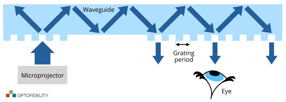
These products are based on exit pupil expanders, an idea patented by Nokia researchers in 2010. Briefly, the exit pupil of a microprojector is placed on the surface of a glass plate, where a grating deflects the light in a large enough angle that it is trapped inside the glass due to total internal reflection. One or two additional gratings are then used to gradually extract the light, making displaced copies of the exit pupi. The result is a large apparent window into the augmented reality for the user to look through. Another immediate advantage of this technique is that exact eye position is no longer critical, and users with varying interpupillary distances (IPD) can be accommodated.
However, producing a satisfying user experience – ensured by a sufficient image uniformity, contrast and brightness – necessitates an extremely accurate nanofabrication process for the diffractive gratings. In order to produce a uniform brightness throughout the displayed image, grating characteristics must be varied within a given grating. Verifying that the produced gratings meet the strict standards of quality can only be accomplished through precise measurements.
Diffraction gratings
When a beam of light hits a diffractive grating, the beam is split into several weaker copies of itself (diffraction orders), propagating in different directions. For line gratings, the period of the grating (line spacing) dictates the output angle of the diffracted beams. The diffraction direction is normal to the grating lines, and the efficiency of all diffraction orders depends on the shape and height of the grating cross-sectional profile.
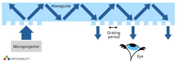
Figure 1. A simplified schematic of a diffractive exit pupil expander. A surface relief grating diffracts incident light into multiple diffraction orders. The directions are dictated by the length of the grating period. If the angle is large enough, light undergoes total internal reflection and is trapped inside the flat glass waveguide. It can then be gradually extracted by another grating, expanding the initial beam to a desired size.
As the features of the waveguide gratings can be smaller than the wavelength of visible light, characterizing the gratings is challenging. For example, optical microscopy does not have the resolution or throughput to accurately characterize large area AR waveguide gratings.
Optimally, the exact shape and orientation of the grating lines could be measured throughout the surface area of the grating. In principle, one can illuminate the grating with a laser and construct a diffractometer to measure the intensity and angle of all diffracted orders. With a good initial guess of the grating shape, the grating profile can be calculated from measurement data by solving a so-called inverse diffraction problem. There are also interferometric techniques.
In the case of diffractive waveguide gratings, capturing the light trapped inside a waveguide is difficult. This can be done by placing a prism into contact with the waveguide via an index matching oil, but the method is not suitable for large scale testing. Furthermore, short-period gratings do not produce many measurable diffraction orders.
The most accurate method for determining the shape of a grating is physically cutting the grating and observing the cross-sectional profile directly via a scanning electron microscope (SEM). Unfortunately, the method damages the investigated sample, and, due to its slow speed, can only be used to characterize a tiny portion of a given grating, making SEM unfit for large-scale quality testing.
Period and orientation measurements
Fortunately, the most important parameter for AR displays is the direction of the diffracted beam, which is only affected by the grating period and orientation, not by the deviations of the grating profile from the designed shape. To characterize these properties, it is sufficient to measure the propagation angle of a single diffraction order. Even light reflected by the grating – as opposed to light trapped inside the waveguide – can be used, making the realization of a measurement system much simpler. In principle, only a light source, a detector, and a way to measure the angle between them and the orientation of the grating are needed.
As light propagates a relatively long distance through several gratings in the waveguide, the required tolerances for the grating periods can be surprisingly strict, in the order of picometers. Likewise, the relative orientations of gratings must be known to a high degree of certainty. OptoFidelity has developed automated testing solutions meeting these demands. If the light source and the detector are placed far apart, measuring the angle between them with the required accuracy becomes very challenging. An often-used method for overcoming this limitation is the so-called Littrow configuration, where the grating is rotated such that the diffraction order of interest is reflected back to the light source. Via a beam splitter, the beam can be steered onto a camera. If the sample rotation stage is first calibrated by observing direct reflection from the grating, we have a very accurate diffraction angle measurement system. Period measurement accuracies below 10 picometers have been reported for Littrow diffractometers.
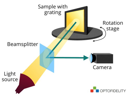 Figure 2. A Littrow diffractometer. A collimated beam illuminates the sample and the diffracted beam is reflected back into the camera.
In addition to the grating period, also the line orientation can be determined by the same measurement, provided that the sample stage has yaw, pitch and rotation control. However, as the measurement results are calculated from the readings of the stage encoders, high mechanical accuracy is required.
At the moment the industry has not standardized on a waveguide grating configuration for AR displays. OptoFidelity, adapting to client’s requirements, is well prepared to fulfill the stringent demands described above and has the expertise to deliver complete grating testing solutions.
In addition to optimizing the waveguide gratings, the final imaging performance of the complete AR display component also needs to be verified.
Author:
Janne Simonen
PhD, Optical Engineer & Technical Lead at OptoFidelity Ltd.
Text contributed by Mr. Janne Hyyti, Optical Engineer at OptoFidelity Ltd.


