Blogs
Imaging Augmented Reality Displays
OptoFidelity testing approach
OptoFidelity through its history has been mimicking human perception by designing sensors and actuators to “replace” human senses and touches. For example, in area of touch testing there has been fingertips with specific materials to mimic softness or capacitance of fingertip or added sensors to sense force or haptics. Sometimes the requirement has been to press touch screen with 1g force in 10um accuracy in XY location or recognize setting icon or read Arabic text.
First step to solve any human mimicking testing challenges is to understand how well the human motoric and vision system performs. What resolution human can sense (see, hear or feel) or actuate? Not to forget that for testing purposes, we need to design a system that can perform multiple times better than human and in more repeatable manner.
Achieving the requirement of repeatable testing, we need to accurately and repeatably know the device under test (DUT) location. What is the point of fancy sensors and actuators, if you do not know the exact point you are testing, or you cannot reproduce? Therefore, more than 95% of OptoFidelity test systems include high precision imaging system combined with matching motion system. Most of system design challenges are related to accurate positioning. Imaging Augmented Reality (AR) displays is not an exception. We need to know exactly where and which direction we are looking and what angle the input image is projected.
Designing imaging system for Augmented Reality Display imaging
First step for AR display imaging is to design optical system that is mimicking the human eye. Special feature of human eye is wide field of view and pupil location at the front surface. Field of view (FOV) of human eye is roughly 90deg. FOV can be often considered to be even higher as brain can combine data from both eyes. Even so, 90deg has been the target value for good immersion.
AR devices are designed to have output pupils in such a distance and locations, that mechanically design can accommodate as many head shapes and sizes as possible. Waveguide is pupil replicator so there are multiple output pupils in the plane on designed distance. Output pupil distance of AR device is called eye relief. Image from AR device can be seen around eye relief distance, but to achieve comparable measurement between samples the distance needs to be consistent between measurements.
Device output pupil is replicated to plane to accommodate different head shapes with different inter-pupil distances. Inter-pupillary distance means distance between eyes measured from pupil.
Human eye input pupil, which is also known as entrance pupil, is at the front surface of the eye. In the normal commercial wide field of view lenses the pupil is deep inside the mechanical lens structure. Pupil location inside optics often causes physical restrictions to move input pupil of the imaging system to device's eye relief distance. Human eye also has variable focusing distance and pupil size, which needs to be considered, while designing imaging system. Pupil size varies in different illumination conditions between 1mm to 8mm. Less light requires larger pupil size and vice versa.
Imaging options: Stitching and Single Shot
There are two alternatives to do AR device imaging: stitching and single shot.
Stitching is using small field of view lens and reconstruct the full Field of View (FOV) image by rotating around pupil centre and scanning the full scene of AR device. Benefit of small FOV scanning imaging is the high resolution you can achieve easily. When FOV is smaller, you can achieve higher angular resolution with smaller resolution camera. Resolution is needed, if you would like to optimize your MTF measurement.
Downside of the scanning approach is the speed (tact time) and possibly the pivoting accuracy. Accuracy is important, because with diffraction gratings there will be some color and brightness variation, if you move 500um. Color variation introduced by measurement system is something to avoid, while targeting to repeatable measurement system. Tact time is lower as the system needs to pivot to multiple locations.
Single shot is using large field of view. Naturally the benefit is the speed and downside is the resolution. Resolution limitation comes from the optics and from available sensor resolution. Good target resolution is 1arcmin (1/60 degree), which has been often considered as human eye resolution. There are studies that Human eye has been able to separate even smaller motions, but it is good starting point.
OptoFidelity has been selecting the single shot approach to offer image quality measurements and inspection for mass production applications. OptoFidelity AR imaging system is called as HMD Eye.
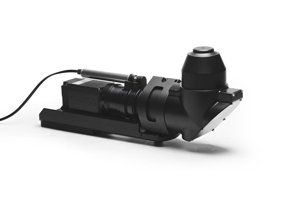
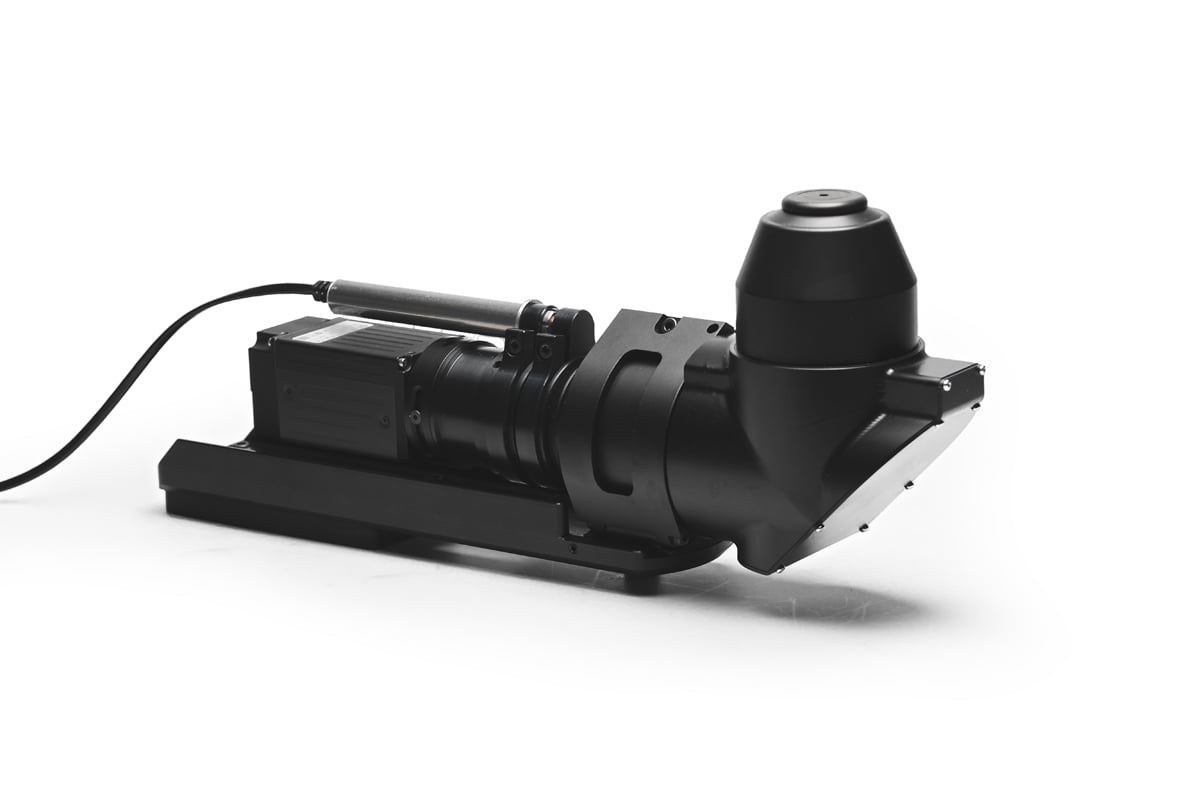 Figure 1: Image of HMD Eye folded design with motorized focus and changeable aperture.
Knowing what you measure and where
Whatever imaging system you select, you need to make sure you know where you are measuring and how to repeat that. Measurement location can rely on physical design or the optical performance of the device under test.
Physical location-based measurements are faster and therefore more suitable for production environment, than the eye box scanning. Eye box scanning is based on FOV or contrast drops at the edge of the eye box. Physical design-based positioning uses sensors to detect XYZ fiducials on the device under test. Fiducial can be part of the device design like gratings or additional positioning markers to make the position easier.
After your camera system is aligned with DUT and possible image reconstruction, it will be another layer of complexity to draw the lines between the measurement results and device design parameters.
OptoFidelity's experts are at your service!
Read more about our offering for AR and VR HMD Testing and become familiar with OptoFidelity HMD IQ and OptoFidelity BUDDY - both ready made products for testing AR, VR & MR HMD image quality and performance.
Should you have any questions or needs in terms of testing or calibrating your products in any phase of the product's lifecycle, our experts are happy to help you! Contact us today at sales@optofidelity.com or give us a call at +358 44 430 0100


